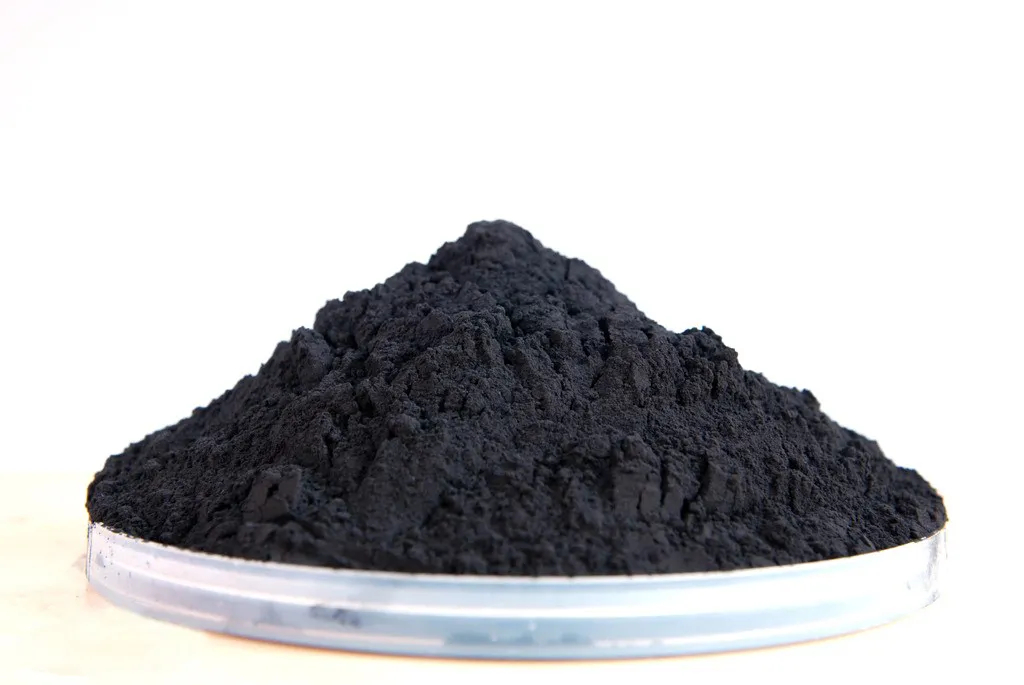
Lithium Iron Phosphate (LiFePO₄, LFP)
Lithium iron phosphate is a key cathode material in lithium-ion batteries. It’s popular in power batteries, energy storage, and consumer electronics. This is thanks to its high safety, low cost, great structural stability, and eco-friendliness. Particle size and particle size distribution (PSD) greatly affect electrochemical and processing performance. They directly influence lithium-ion diffusion rate, electrode compaction density, and slurry stability. This, in turn, impacts the battery’s energy density, cycle life, and rate capability. Reducing particle size shortens the lithium-ion diffusion path in the LFP lattice. This improves low-temperature discharge performance. However, if the particles are too fine, they can agglomerate and lower compaction density. Controlling LFP particle size during pulverization is key. It helps balance material performance and processing ease.
Jet Mill
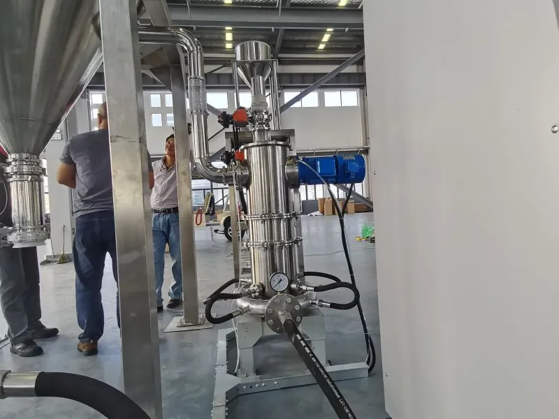
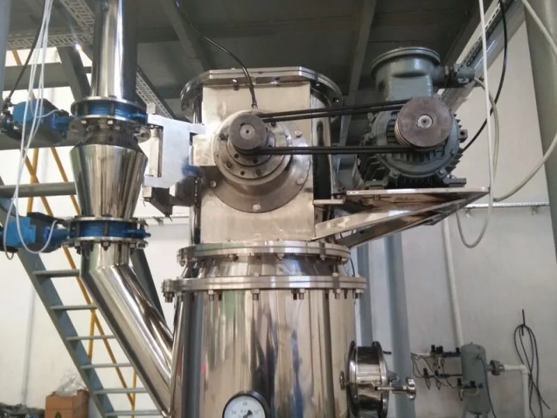
An air jet mill is a machine that crushes materials into superfine particles. It uses high-speed gas jets for this process. It uses supersonic airflow to speed up particles. These particles collide with each other, the chamber wall, or impact plates to achieve pulverization. This is different from traditional mechanical mills. The system’s turbo classifier quickly sorts qualified particles from coarse ones. Coarse particles go back to the grinding chamber for re-pulverization. This creates a closed-loop process. This equipment is great for LFP pulverization. It offers high grinding efficiency, narrow PSD control, and low contamination. Plus, it works well with inert gas protection to stop material oxidation.
The main parts of an air jet mill system are:
- Air compressor
- Feeding system
- Grinding host
- Classifier
- Dust collector
- Control system
- Inert gas protection unit
Particle Size Control in LFP Pulverization
Particle size control is about adjusting operational settings and conditions in air jet milling. This process aims to produce LFP powder that meets specific particle size targets. These targets include characteristic diameters (D10, D50, D90) and the particle size distribution (PSD) span, calculated as (D90-D10)/D50. Industry standards typically require LFP D50 to be in the range of 1-3 μm, D90 ≤ 5 μm, and span ≤ 1.2 for optimal battery performance. This control process relies on several factors. These include raw material properties, equipment settings, and environmental conditions. Real-time monitoring and quick adjustments are needed to keep everything consistent and stable.
How Do Interactive Effects of Jet Milling Parameters Influence LFP Particle Size?
The particle size of LFP from an air jet mill isn’t set by one factor. Instead, it depends on several key operational parameters. The most important ones are grinding pressure, classifier wheel speed, and feed rate.
Grinding pressure affects airflow and particle speed. Higher pressure boosts particle movement, increasing collision energy and crushing efficiency. This often leads to a lower D50 and a narrower PSD. Too much pressure (over 0.6 MPa) can cause over-grinding. This leads to particle clumping because the specific surface area and surface energy increase. The standard grinding pressure for LFP is usually 0.4-0.5 MPa, with an allowable fluctuation of ±100 kPa.
Classifier wheel speed is key for separating qualified particles. When speed increases, it boosts centrifugal force in the classification chamber. This allows only finer particles to pass through, which reduces product D50. Conversely, lower speed results in coarser product particle size. The standard frequency of the classifier wheel is typically set with a tolerance of ±5 Hz to maintain PSD stability. For example, when targeting D50 = 1 μm, the classifier wheel frequency is usually adjusted to 35-45 Hz, depending on the equipment model.
Feed rate impacts how long material stays in the grinding chamber. A lower feed rate means longer grinding times, which produces finer particles. A higher feed rate lowers grinding efficiency. This results in coarser particles and a wider particle size distribution (PSD). Experiments show that setting the grinding pressure to 0.5 MPa and cutting the feed rate from 1.25 kg/h to 0.5 kg/h can reduce the LFP D50 from 4.2 μm to 1.8 μm. This change also narrows the span from 1.5 to 1.1. A feed rate that’s too low hurts production efficiency and can lead to over-grinding. So, it’s important to match the optimal feed rate with grinding pressure and classifier speed.
How to Mitigate Particle Agglomeration During LFP Jet Milling?
Agglomeration is a common issue in LFP superfine pulverization. Finer particles stick together because of van der Waals forces and electrostatic interactions. This clumping worsens the particle size distribution (PSD) and lowers electrode performance. Mitigation measures mainly involve optimizing process conditions and adopting auxiliary technologies:
Firstly, inert gas protection is essential. Purge the whole milling system with high-purity nitrogen. Make sure the oxygen content is ≤ 50 ppm. This helps prevent LFP oxidation and cuts down on electrostatic buildup. Meanwhile, controlling the dew point of the grinding air to ≤ -20 °C avoids moisture absorption, which is a major cause of agglomeration. Closed-loop nitrogen conveying keeps a stable processing environment. It also reduces particle contact with outside contaminants.
Secondly, adjusting process parameters to avoid over-grinding. Over-grinding increases the specific surface area of LFP particles, significantly enhancing agglomeration tendency. You can achieve this by matching the feed rate and grinding pressure. This way, particles will be crushed to the right size without too much processing. When LFP D50 hits 1-2 μm, increasing grinding pressure or residence time will cause agglomeration.
Thirdly, post-milling dispersion treatment. Adding the right amount of dispersant when making slurry can lower particle surface energy and break up agglomerates. Experiments show that when the dispersant content hits 0.8% of the LFP mass, the D50 of the slurry drops from 3.5 μm to 1.6 μm. Also, the PSD starts to stabilize. Also, using a 200-mesh sieve to screen the milled powder removes large clumps. This helps make the product more uniform.
Benefits of Precise Particle Size Control
Enhanced Electrochemical Performance
Controlling particle size helps improve lithium-ion movement and the structure of LFP electrodes. Reducing D50 to the ideal range of 1-3 μm shortens the lithium-ion path in the lattice. This enhances the material’s rate capability and boosts its performance at low temperatures. For instance, LFP with D50 = 2 μm shows a 0.1C discharge specific capacity of 158 mAh/g at -20 °C, which is 22% higher than that of LFP with D50 = 5 μm . A narrow PSD (span ≤ 1.2) helps pack particles evenly in the electrode. This lowers internal resistance and boosts cycle stability. Tests show that LFP with controlled particle size keeps 95% of its initial capacity after 1000 cycles at a 1C rate. In contrast, samples with a wide PSD only retain 83%.
Improved Processing Performance
Controlled particle size enhances the processability of LFP in electrode manufacturing. A good PSD, where fine particles fill the gaps between coarse ones, boosts the compaction density of the electrode sheet. For power and energy storage batteries, the electrode compaction density can rise from 2.17 g/cm³ (unmilled LFP) to 2.45 g/cm³ (optimally milled LFP). This boost greatly enhances the volume energy density. Properly sized LFP particles help keep slurry viscosity and fluidity stable. This prevents issues like uneven coating and cracking of electrodes during processing. This reduces production defects and improves the consistency of battery cells.
Cost Reduction and Quality Consistency
Controlling particle size helps cut production costs in two ways. First, the air jet mill’s closed-loop system limits material loss, achieving a yield rate over 98%. Second, by optimizing settings, we avoid over-grinding, which lowers energy use. This can cut air compressor power by 15-20% compared to less controlled methods. Real-time monitoring and feedback control, through LIMS and SPC systems, ensure consistent LFP particle size. This meets the strict quality standards of the battery industry, like ISO/TS 16949 and IATF 16949. This reduces quality inspection costs and the risk of batch scrapping.
Broadened Application Adaptability
Different battery uses need certain LFP particle sizes. Power batteries for electric vehicles need a D50 of 1-2 μm. This size balances rate capability and energy density. In contrast, energy storage batteries can use a D50 of 2-3 μm. This larger size focuses on cycle life and cost. Controlling particle size precisely lets us customize LFP production to fit different application needs. By changing the classifier speed and feed rate, the air jet mill can make LFP with a D50 from 0.8 μm to 5 μm. It can power both high-performance consumer electronics and large-scale energy storage systems.
Step-by-Step Operation Guide
Pre-Milling Preparation
Raw Material Treatment
First, check the sintered LFP raw material. Make sure the Fe/P molar ratio is between 0.995 and 1.005. Also, harmful metal impurities (Na, K, Ca) should total no more than 100 ppm. Finally, confirm the initial particle size is 1 mm or smaller. Dry the raw material in a vacuum dryer at 120 °C for 2 hours. This will reduce moisture content to ≤ 0.1%. Moisture can cause agglomeration and oxidation during milling. Move the dried material to the raw material silo using closed-loop nitrogen protection. Keep a micro-positive pressure of 3-10 kPa in the silo to stop air from entering.
Equipment Inspection and Calibration
Check the air jet mill system’s integrity. Inspect the tightness of pipelines to prevent air leaks. Check the nozzles for wear; replace them if they are worn to maintain uniform airflow. Also, clean the classifier chamber by removing any leftover material from previous batches.
Calibrate key instruments:
- Use a laser particle size analyzer, calibrated with standard particles, for accurate PSD measurement.
- Verify the pressure gauge, temperature sensor, and frequency converter (for classifier and feeder) to ensure errors stay within ±2%.
Inert Gas Purging
Purge the whole system—grinding chamber, classifier, dust collector, and pipelines—with high-purity nitrogen (≥ 99.999%) for 30 minutes. Monitor the oxygen content in the grinding chamber using an online detector, ensuring it drops to ≤ 50 ppm before starting milling. Adjust the nitrogen dew point to ≤ -20 °C using a dryer to prevent moisture accumulation.
Milling Parameter Setting and Startup
Parameter Initialization
Set initial parameters for the target particle size (using D50 = 2 μm):
- Grinding pressure: 0.5 MPa
- Air source temperature: 120 °C
- Classifier wheel frequency: 40 Hz
- Feed rate: 0.75 kg/h
- Discharge feeder frequency: 30 Hz
Start the air compressor and heating system. Preheat the mill for 1 hour. This stabilizes airflow temperature and pressure.
Trial Milling and Parameter Optimization
Initiate trial milling with a small batch (5 kg) of raw material. Collect samples every 10 minutes and test PSD using a laser particle size analyzer. Adjust parameters dynamically based on test results:
- If D50 > target: Increase grinding pressure by 0.05 MPa or classifier frequency by 2 Hz, or reduce feed rate by 0.1 kg/h;
- If D50 < target: Decrease grinding pressure by 0.05 MPa or classifier frequency by 2 Hz, or increase feed rate by 0.1 kg/h;
- If span > 1.2: Adjust feed rate to be 10% lower than the current value and increase classifier frequency by 3 Hz to narrow PSD.
Repeat trial milling until the PSD meets the target (D50 = 2 ± 0.2 μm, D90 ≤ 5 μm, span ≤ 1.2), then fix the parameters for formal production.
Formal Milling and Real-Time Monitoring
Start the screw feeder to convey raw material from the silo to the grinding chamber at the set feed rate. Ensure steady nitrogen flow and pressure during the process. Monitor key parameters in real-time using the PLC control system. Keep grinding pressure fluctuations within ±100 kPa. Classifier frequency should vary by no more than ±5 Hz. Oxygen content must stay at or below 50 ppm. Maintain the silo material level between 1/3 and 2/3.
Collect product samples every 30 minutes for PSD testing and record data in the LIMS system. Inspect the dust collector and discharge system every hour. This helps ensure smooth operation and prevents material buildup.
Post-Milling Treatment
Product Collection and Screening
The filter cartridge dust collector gathers the qualified LFP powder. Then, it discharges the powder through a butterfly valve. Sift the powder using a 200-mesh sieve to get rid of large clumps. Collect the fine powder as your final product. Recycle the oversize to the raw material silo for re-milling to improve yield.
Packaging and Storage
Package the final product in moisture-proof aluminum foil bags. Use nitrogen protection to keep moisture content at or below 0.1%. Label each package with batch number, production time, PSD parameters, and test results. Store packaged products in a dehumidified room. Keep the humidity below 30% to avoid moisture absorption.
Equipment Shutdown and Maintenance
After production, first stop the feed. Then, keep supplying nitrogen for 20 minutes to clear out any leftover material in the system. Shut down the air compressor, heater, and classifier sequentially. Clean the grinding chamber, classifier, and pipelines using nitrogen. This prevents cross-contamination between batches.
- Inspect and maintain equipment.
- Replace worn nozzles.
- Clean the filter cartridge.
- Calibrate instruments for the next use.
Practical Application Results
Large-Scale Production of High-Power Battery LFP
An Australian chemical factory installed an ALPA air jet mill to make LFP for electric vehicle batteries. They aimed for D50 = 1 μm and a production capacity of 2 T/H. Key parameters were optimized:
- Grinding pressure: 0.55 MPa
- Classifier frequency: 45 Hz
- Feed rate: 1.0 kg/h
- Nitrogen dew point: -25 °C
- Oxygen content: 30 ppm
After 72 hours of continuous production, the test results showed:
- Average D50 = 1.02 ± 0.08 μm
- D90 = 4.2 μm
- Span = 1.15
These results meet the target requirements.
The LFP was formed into 6 Ah pouch cells. These cells showed a 1C discharge specific capacity of 160 mAh/g. At low temperatures (-20 °C), they retained 85% of their discharge capacity. They also had a cycle life of 1500 cycles, maintaining at least 90% capacity retention. Energy use per ton of LFP dropped by 18% compared to the old process. Also, the product qualification rate rose from 89% to 99.2%.
Laboratory-Scale Optimization for Energy Storage Batteries
A research team optimized LFP particle size using an MSK-SFM-AF air jet mill. They aimed to balance cycle life and cost, targeting a D50 of 2.5 μm for energy storage batteries. The raw material started with a D50 of 16.3 μm. We adjusted the milling parameters using orthogonal experiments. The feed rate ranged from 0.5 to 1.25 kg/h. Grinding pressure varied between 0.4 and 0.6 MPa. Classifier frequency was set from 35 to 45 Hz.
The optimal parameters were determined as feed rate = 0.75 kg/h, grinding pressure = 0.45 MPa, classifier frequency = 38 Hz. The resulting LFP had D50 = 2.48 μm, D90 = 4.8 μm, span = 1.18. The electrode compaction density reached 2.42 g/cm³, 11.5% higher than the unmilled sample. The energy storage battery modules lasted for 3000 cycles, keeping at least 88% capacity. They also had a discharge rate capability of 2C, retaining over 95% capacity. This makes them suitable for large-scale energy storage systems.
Agglomeration Control for Ultra-Fine LFP
A Chinese battery material manufacturer encountered severe agglomeration when producing LFP with D50 = 0.8 μm.
The improvement measures included:
- Optimizing nitrogen flow to boost particle dispersion.
- Adding 0.8% polycarboxylate dispersant during post-milling slurry prep.
- Adjusting the classifier frequency to 48 Hz to prevent over-grinding.
After improvement, the agglomeration rate of LFP dropped from 28% to 5%. The PSD stabilized at D50 = 0.82 ± 0.06 μm, with a span of 1.12. The slurry viscosity (at 60% solid content) decreased from 3500 mPa·s to 2200 mPa·s, improving coating uniformity. The final battery cells had a 0.1C discharge capacity of 162 mAh/g. They also showed great rate performance, with a 5C discharge capacity retention of 80% or more. This makes them ideal for high-performance consumer electronics.
Controlling the particle size of LFP from an air jet mill involves several steps. First, treat the raw materials. Then, optimize the parameters. Next, monitor the process in real time. Finally, perform post-processing. The key is to understand how grinding pressure, classifier speed, and feed rate interact. Also, using inert gas protection and dispersion methods can help reduce agglomeration. Controlling particle size carefully improves the performance of LFP. It also cuts production costs and expands its range of uses.